
Highway Drainage: Need and Types of Highway Drainage System!
Highway drainage consists of removing or controlling surface water and subsurface water away from the road surface and the subgrade supporting it. Part of the rain water flows on the ground or road surface, while the other part percolates into the ground and reaches the ground water table, raising its level. The subgrade soil above the ground water table may raise through the soil pores due to the phenomenon of capillarity.
Need and Importance of Highway Drainage:
The continued presence of water on the road surface weakens the pavement causing pot holes and ruts; similarly, the presence of water in the subgrade reduces its bearing power and load dispersion capacity. Loss of subgrade support leads to the failure of the road pavement under traffic loads. Hence efficient drainage is an imperative need.
Lack of drainage or inadequate drainage has been the primary reason for the failure of highway pavements. The importance of drainage in the successful maintenance and operation of highways is reflected in the adage- “There are just three factors necessary for a good road: drainage, drainage and more drainage.”
ADVERTISEMENTS:
Road builders of ancient era like the Romans and Aryans themselves understood the importance of drainage; pioneers of the modern era like MacAdam, Telford and Tresaguet also appreciated the need of good drainage for the success of a roadway.
In fact, constructing an efficient drainage system for the road is considered to be a cheaper, yet effective method to enhance its life than the current practice of the designing pavements for soaked subgrade conditions, which leads to the formation of thicker road sections.
Types of Highway Drainage:
In the hydrologic cycle, a part of the total precipitation or rainfall runs on the ground surface. This portion, called surface runoff, gets collected in tanks, lakes, reservoirs, and other such water-bodies. A part of this surface run-off forms streams and joins running water in the form of rivers, which eventually join the seas and oceans. All these constitute surface water.
Similarly, the remaining part percolates into the ground surface where favourable conditions of permeability exist; these waters join the ground water table and ground water reservoirs, raising the ground water table. In the dry summer season, ground water level rises due to capillarity.
ADVERTISEMENTS:
However, the exploitation of ground water by humans depletes the ground water and lowers the ground water table. Once again, during rainy season, it gets recharged by percolation, raising the ground water table.
The three principal types of highway drainage are:
1. Surface drainage
2. Subsurface drainage
ADVERTISEMENTS:
3. Cross drainage
Requirements of a Good Drainage System:
A good drainage system should prevent the following ill-effects of excess surface water and of ground water on the pavement and on the subgrade:
1. Reduction of the strength of the pavement.
ADVERTISEMENTS:
2. Spoiling the pavement surface by the formation of pot-holes and ruts.
3. Seeping of surface water through the pavement layers, shoulders and the sides into the subgrade.
4. Reduction in the bearing power of the subgrade through continued presence of water.
5. Volume changes in the subgrade and consequent settlements and deleterious effects.
ADVERTISEMENTS:
6. Soil erosion around the pavement.
7. Slope failures in the case of cuttings and embankments for the roads.
8. Capillarity and frost action, weakening the subgrade.
Drainage and Geometric Design Aspects:
The following geometric design aspects of highways are fully or partly governed by the requirements of drainage:
1. Longitudinal gradient
2. Cross-fall or camber
3. Vertical curves – summits and sags
4. Shoulders
5. Medians
6. Embankments
7. Intersections
8. Rotaries
9. Fly-overs
Some of the above features are also relevant to urban roads.
1. Surface Drainage:
Surface drainage consists of the arrangements made for the quick and effective draining of water that collects on the pavement surface, shoulders, slopes of embankments and cuttings and adjoining land up to the right of way. This water is let off into natural or artificial channels sufficiently farther away such that the functioning of the highway is not impeded in any manner.
The sources of surface water are precipitation of different kinds such as rain, snow, drizzle, hail and sleet. Waste water from irrigation is also a possible source. Snow fall and melting ice are common sources in the plains at the foothills of the Himalayas.
Hydrological Aspects:
The intensity of rainfall, frequency and duration are important factors which contribute to surface run-off. Storms, especially severe ones, do not occur frequently, but occur in a cyclic manner. The design return period governs the intensity of rainfall to be considered for design.
IRC recommends that a return period 1 to 2 years be adopted for the estimation of run-off (IRC: SP: 42-1994: Guidelines on road drainage and IRC: SP: 50-1999: Guidelines on urban drainage). IRC also recommends that the storm duration be chosen as equal to the ‘time of concentration’, which is the ‘time required for a given drop of water from the remotest part of the catchment to reach the point of exit’.
The time of concentration comprises two components – entry time and time of flow, which can be easily understood from Fig. 8.15.

“IRC: SP: 42-1994” gives the following chart for estimating the time of concentration (Fig. 8.16):

For reliable estimation of critical intensity of rainfall, it would be ideal to have rainfall records at short intervals—5, 10, 20, 30, 40, 50, and 60 minutes.
Alternatively, IRC: SP: 42 recommends the following equation –
(T + 1/t + 1) … (8.7)
Where, i = intensity of rainfall (cm) occurring in a short period of t hours.
R = total intensity of rainfall (cm) occurring in a storm of total duration of T hours.
t = shorter duration of time interval (hrs) within the storm of total duration of T hours.
(This may be taken to be the time of concentration, tc).
This is applicable for shorter duration of rainfall ≤ 120 minutes.
The entry time loses its importance as the length of the drain increases, as the former becomes a small part of the time of concentration.
The time of concentration, t may be determined from the following empirical equation:

Estimation of Run-Off:
The quantity of surface water to be drained off is required designing the size of storm water drain.
All the rainfall which falls on the catchment area will not reach the point of consideration for the design of the drainage facility. In between, percolation and evaporation losses occur; these losses are governed by factors such as soil type, vegetative cover, slope of the catchment, distance of travel, land-use details and temperature.
The following formula, called the rational formula is recommended by “IRC: SP: 13-1973- (2004 Revised): Guidelines for the Design of Small Bridges and Culverts, IRC, New Delhi, 2004.”–
![]()
Where,
Q = Peak run-off (m3/second);
C = Coefficient of run-off which depends on the type of surface (C-value ranges from 0.90 for impervious surfaces like city pavements to 0.10 for clay soil covered with heavy vegetation);
i = critical intensity of rainfall in cm/hr occurring during the time of concentration (tc), and for the chosen frequency interval or return period; and
A = catchment area or area of drainage in hectares
[C is actually the ratio of run-off to the intensity of rainfall.]
The values given in Table 8.29 are suggested for the coefficient of run-off, C [IRC: SP: 13-2004 (Revised); IRC: SP: 42-1994; and IRC: SP: 50-1999] –
When the catchment area consists of different types of surfaces with different run-off coefficients, the weighted average value is taken for C –
![]()
(Here, A1, A2, … are the areas with different run-off coefficients C1, C2 ….).
The India Meteorological Department provides Intensity-Duration-Frequency (IDF) curves for any given locality as contours of 1 hour rainfall intensity for frequency periods of 2, 5, 10, 25 and 50 years. Longer frequency periods of 25 years and above are considered for primary roads like national highways, whereas suitable shorter frequency periods are chosen for secondary and tertiary roads.

A return period of 10 years and above is considered adequate for the design of highway drainage facilities.
The design run off may be obtained by multiplying the 1 hour rainfall intensity for the specific locality for the chosen frequency period, by a suitable empirical conversion factor.
Hydraulic Design of Drains:
Side drains in cuttings and longitudinal drains along the edge of embankment are meant to lead the run-off to natural water outlets. Hence, these have to be hydraulically designed to fulfill their function efficiently. Principles of open channel flow are used.
The sectional area of the drain may be determined from the discharge equation as-

Where,
V = velocity (m/sec)
n = Manning’s coefficient of rugosity (depends on the roughness of the surface)
R = hydraulic mean depth (= A/P, where A is the area of flow and P is the wetted perimeter)
S = longitudinal bed slope of the channel or drain.
The recommended value of Manning’s n and the maximum permissible velocity V are given in IRC: SP: 42-1994 for different surfaces of the drain and set forth in Table 8.30. [n ranges from 0.012 to 0.2 and V ranges from 0.3 to 6 m/s.].

Critical Depth:
Open channels of drains are designed with reference to critical conditions of flow – the state at which flow takes place at minimum specific energy. The depth of flow at minimum specific energy is called the critical depth of flow (dc). The depth of flow for any mild slope, greater than the critical depth is called the normal depth of flow (dn).
The critical depth provides boundary conditions for upstream as super-critical flow and downstream as sub-critical flow. To allow greater area of flow and hence greater discharge, the depth of flow should be greater than the critical depth of flow. At this condition, the flow will be sub-critical since the velocity is smaller than the critical value.
Hence, the slope and cross-section of a channel should be designed to satisfy the criterion dm > dc.
The basic governing formula for determining the critical depth is-
Q2/g = A3/T … (8.13)
Where,
Q = discharge
A = area of flow
T = top width of flow
g = acceleration due to gravity.
For a rectangular cross-section of width, B, and the critical depth, dc, as depth of flow,

Equation (8.15) has to be solved by trial and error for the depth of flow for the allowable velocity and assumed bed slope.
The depth of flow should be more than the critical depth and should be verified. If the desired depth is not achieved, the section has to be redesigned by changing the bed slope suitably.
If these conditions cannot be satisfied easily, the drain may be paved with a lining such as concrete/cement mortar to reduce the roughness coefficient and increase the permissible velocity.
Procedure for Design of Open Drains:
The following are the steps for designing open drains:
1. For the known soil conditions, calculate the Manning’s rugosity coefficient, side slopes, and the maximum permissible velocity.
2. Determine the slope of the drain from the topography.
3. For the runoff or discharge expected to be drained, calculate the hydraulic mean depth using Manning’s formula.
4. Calculate the cross-sectional area from the discharge and the maximum permissible velocity.
5. From the result of (3) and (4), solve the two simultaneous equations to obtain the bottom width and depth.
6. Calculate the critical depth and determine whether the flow is streamlined or turbulent. If the flow is streamlined, add a free board to the depth and finalise the cross-section. If the flow is turbulent, it may be necessary to decrease the longitudinal slope, or line the channel.
Moisture changes in the subgrade occur due to percolation of rain water and seepage flow, as also due to the phenomenon of capillary rise. The aim of subsurface drainage is to keep the ground water table (GWT) sufficiently below the level of the subgrade – at least 1.2 m.
When the water table is almost at the natural ground surface, the best option is to raise the formation of the roadway on an embankment, such that it is 1.2 m above the ground. If this is not possible for the reason of unfavourable topography, the only option is to lower the ground water table by means of subsurface drainage arrangements. It must, however, be remembered that only gravitational water in the soil can be drained, but not ‘held water’, which is made up of the moisture film around the grains.
A few drainage arrangements for different situations are discussed below:
Subgrade Drain:
One option is to install a drain in the pervious layer besides the road to intercept the ground water before it can reach the subgrade, as shown in Fig. 8.17.

Longitudinal Drain Trenches and Pipes:
If the soil is relatively pervious, longitudinal drainage trenches with drain pipe, backfilled with filter sand can be used. The depth of the trench depends on the extent of lowering required, soil type, and distance between the trenches. A typical arrangement is shown in Fig. 8.18.

Longitudinal and Transverse Drains for Lowering GWT:
If the soil is relatively less permeable, longitudinal as well as transverse drains may be needed to lower the ground water table as shown in Fig. 8.19.

Capillary Cut-Off for Clayey Subgrade:
If the subgrade is clayey, the system of sub-surface drains on either side will not be effective, in view of very low permeability of the subgrade. In such a case the subgrade has to be raised with a free-draining material, or a capillary cut-off has to be applied as shown in Fig. 8.20.

The capillary cut-off may even be an impermeable bituminous layer.
The location of the cut-off should be above the level of capillary rise expected for the clayey subgrade.
Sub-Surface Drains to Control Seepage in Cut Slopes:
Sometimes, seepage water renders cut slopes unstable by reaching the face of the slope. This can be prevented by lowering the seepage line by providing a sub-surface longitudinal drain installed to a depth below the pervious layer as shown in Fig. 8.21.

If the depth of pervious layer is more, horizontal drains comprising perforated metallic pipes or PVC pipes installed at a suitable slope may be provided to serve the same purpose.
Drain Pipes and Filter Media:
A subsurface drain may comprise of perforated pipe, a porous concrete pipe or solid pipe laid with open joints. Alternatively, a trench filled with a free draining material may be used to serve the purpose of a drain.
A perforated pipe or a porous pipe (of no fines concrete) with an impervious cap at the top, laid in a trench and backfilled with a granular, free-draining material top is considered to be a good choice.
If granular filter material with appropriate gradation has to be used, it has to be designed to satisfy certain criteria.
Design of a Filter Material:
The gradation requirements of the filter material are based on three criteria:
(i) Permeability of filter
(ii) Prevention of Piping (because of high seepage velocity)
(iii) Prevention of clogging of the drain pipe.
These requirements are:
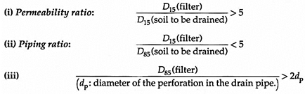
Fig. 8.22 shows an example of the selection of a suitable filter material based on the gradation of the soil to be drained.

Set the grading of the soil to be drained be plotted as shown. Mark the D15 and D85 of the soil. From permeability criterion, mark D15 of filter (>5D15 of soil) as A.
From piping criterion, mark D15 of filter (<5D85 of soil) as B.
On D85 line, mark point C, such that D85 (filter) is greater than 2dp (dp being the diameter of the perforation of the drain pipe).
A suggested grading of filter may be drawn smoothly such that it lies to the left of C and lies between A and B as shown.
The perforated pipe is usually 100 to 150 mm in diameter with holes in two or more lines towards the bottom of the pipe. The collector pipes of porous concrete, metal or PVC should be laid with a minimum of 100 mm of filter sand around them.
Usually 5 mm diameter holes are considered adequate, if restricted to the lower 60° arc of the pipe. Solid pipes with open joints may be used, but care should be taken to see that silt and fine sand do not enter the pipe.
When the flow of water takes place through porous backfill of graded sand, it is likely to be clogged after some time. Hence, this involves maintenance, washing of the clogged backfill and
Geosynthetics in Subsurface Drains:
Geosynthetics or geotextiles are becoming popular as substitutes or alternatives to graded filters. They have high retention fine particles and permeability similar to graded material and good tensile strength. Installation is also easy.
Geosynthetic products perform the functions of a filter as well as that of a separator.
Fig. 8.23 shows an aggregate drain with a pipe encased in a geosynthetic.

3. Cross Drainage:
Roads have to be aligned often as to cross natural drainage channels, streams and major rivers. Sometimes, the alignment will be across man-made channels like those for irrigation.
In such cases, the need for constructing cross drainage structures arises to ensure that the water flows beneath the road without causing any inconvenience or instability to the highway structure.
Types of Cross-drainage Structures:
1. Culverts (waterway less than 6 m)
2. Minor bridges (waterway from 6-30 m)
3. Medium-sized bridges (waterway from 30-100 m)
4. Major bridges (waterway more than 100 m)
5. Causeways
Categories (2) and (3) may also be clubbed and called Minor bridges. Bridges are designed such that they are not submerged even under the highest flood expected in a design period of, say 50 years or 100 years, depending upon the importance of the highway and the bridge.
From the point of view of economy, a bridge may be designed to be submerged and cause interruption of traffic a limited number of days in a year. Such bridges are called submersible bridges.
Culverts:
The popular types of culverts are:
(i) Masonry arch culverts
(ii) Slab culverts (Stone slab or R.C.C. slab with abutments and piers)
(iii) Pipe culverts (Metal pipe, Stoneware pipe, or R.C.C. Hume pipe)
(iv) R.C.C. Box culverts
Bridges:
Bridge engineering is a specialised field.
The following are types of bridges for spans in the increasing order:
(i) Masonry arch
(ii) R.C.C. slab (simply supported)
(iii) R.C.C. T-beam (simply supported)
(iv) Continuous T-beam and slab of R.C.C.
(v) R.C.C. balanced cantilever
(vi) Pre-stressed concrete
(vii) Suspension bridges.
Causeways:
Causeways allow water to flow over them when the stream or water course receives floods. These are provided on relatively unimportant roads with small volume of traffic.
The interruption to traffic on these structures should not be for more than 15 days in a year and not exceed 3 days at a stretch.
Depending upon the degree of interruption, causeways may be called low-level causeways or high-level causeways.
Certain special features are characteristic of urban roads. These are covered exhaustively in the IRC- Special Publication – “IRC: SP: 50-1999; Guidelines on Urban Drainage, Indian Roads Congress, New Delhi, 1999”.
Only a few features are given here briefly:
Shoulder Drainage:
For quick drainage of water from the roadway, the shoulder surface has to be properly sloped. A continuous drainage layer, 75 to 100 mm thick, can be laid under the shoulder at the bottom level of the sub-base or the bottom-most granular sub-base layer and extended up to the edge. A paved shoulder, if provided, should have a cross- slope of at least 0.5% more than the camber; the unpaved shoulder beyond this should be a further 0.5% steeper as shown in Fig. 8.24.

Median Drainage:
Narrow medians may be drained towards the pavement. Medians with a width of up to 1.8 m can be provided with kerbs and paved; those with width ranging from 1.8 to 5 m are usually turfed and crowned for the surface water to run towards the pavement (which may be with or without kerbs). For medians that are more than 5 m wide, there are no kerbs at the edge.
If the carriageway drains towards the median, central drain may be made to carry the run off. At intervals, the drain may also be made to lead water to an outlet.
Drainage of High Embankment:
In the case of high embankments (more than 8 metres high) as with bridge approaches, slopes and shoulders may be eroded by surface run-off. To prevent or minimise this, longitudinal drains are to be provided at the edges of the roadway, from which the water may be led down the slopes by means of lined chutes with energy dissipation basins at the toe.
The water thus collected at the toe can be led in an open toe drain at the bottom parallel to the road, and led to a natural outlet at an appropriate point. In between the chutes, the slope is to be turfed to protect it from surface erosion (Fig. 8.25).

Drainage of Rotaries:
Water, from the large area around a rotary, flows towards the centre of the rotary, because of the super-elevated pavements. This has to be collected and led into the overall drainage system. A typical arrangement is shown in Fig. 8.26.

Similar arrangements can be made at an intersection.
At a flyover, the water collected in longitudinal drains on either side of the pavements can be led thorough the hollows of pillars of the supporting structure like a bridge and led away through a storm water drainage system.