In this article we will discuss about:- 1. Meaning of Clamping Device 2. Basic Rules of Clamping Device 3. Types.
Meaning of Clamping Device:
Clamping Device purpose is to hold work in the correct relative position in the fixture and to ensure that the job is not displaced under cutting forces. It is also necessary for clamping the jig to the work.
The most efficient scheme of clamping means that the clamping should be adequate and at the same time, the clamping device design should be such that the operating time of jig or fixture is least possible. Thus for high rates of production, quick-acting clamps are essential whereas simple clamps may be adequate for small batches of work.
In the design of efficient clamping devices, the following points should be considered:
ADVERTISEMENTS:
(i) The rotary or reciprocating movement of clamp should be avoided as far as possible. If however, the movement of the clamp is necessary, then only positively guided movement should be employed.
(ii) Arrangements should be made to lift the clamp away from the work, or otherwise clear it, when the clamping load is released. This can be achieved by employing compression springs.
Basic Rules of Clamping Device:
Clamping prevents the part from shifting or being pulled from the jig/ fixture during machining:
(i) Clamps should always contact the work at its most rigid point to avoid bending or damage of part by the clamping force. It the clamping force at any point could bend the part, it must be supported suitably at that point (Refer Fig. 28.33).
(ii) Clamps should be positioned such that they do not interfere with the operation of machine/tool and enable operator to work easily and safely.
(iii) Tool forces generated by cutting action should help in holding the work piece instead of lifting or tilting it. The tool forces should be directed at solid part of the tool body.
(iv) The type and amount of clamping force (force required to hold a part against the locators) needed to hold a part is usually determined by the tool forces working on the part and the way the part and the part is positioned in the tool. Clamping pressure should only be enough to hold the part against the locators. The locators should resist the bulk of the thrust. Clamps must never be expected to hold all of the thrust.
Types of Clamping Device:
We will now study the various types of clamps and methods of clamping. Tool designer should choose the clamp which is simpler and easiest to use and most efficient.
1. Lever of Strap Clamps:
ADVERTISEMENTS:
This is the most popular clamping device used in workshops, and tool rooms of jigs and fixtures.
Figs. 28.34 (b), (c) and (d) show lever-type clamps in which the layout is based on Fig. 28.34 (a). In these, as the nut is unscrewed, the spring pushes the clamp upwards. The clamp has a longitudinal slot so that it can be pushed clear of the work. The clamping operation can be speeded up by using a threaded handle or a quick action locking cam in place of hexagonal nut. The mechanical advantage,
Distance between reaction of clamp and clamping force (a):
This distance ‘a’ should never be greater than distance ‘b’. The difference between these three arrangements is due to various ways of forming the heel. In Fig. 28.34 (b), the clamp is forged carrying its own heel.
Clamps of this type are rotated to clear the job when the later is removed from the fixture. Fig. 28.34 (c) shows a lever clamp guided by a loose heel driven into the fixture. The stud turned on the end of the heel passes through an elongated slot and fits loosely into the keyway in the clamp bar.
This is provided so that when a nut is slacked off, the clamp may be drawn back clear of the work in order that the component may be more easily loaded into the fixture. The compression springs beneath the clamps are provided to clamp up against the nut to free the operator from the necessity of picking up the clamp and manoeuvering it over the work. In Fig. 28.34 (d), the body of the fixture is cast to form an integral heel.
Fig. 28.35 shows the hinge clamp, the sliding clamp, and the latch clamp.
The fulcrum is positioned so that clamp bar is parallel to the base of the tool at all times.
Strap clamp can be operated by either manual or power driven devices. Manual devices include hexagonal nuts, hand knobs, and cams (Refer Fig. 28.36).
The holding power of a strap clamp is determined by the size of the threaded member binding the clamp.
2. Screw Clamps:
These are widely used for jigs and fixtures. These have lower costs. However, their operating speed is quite slow. The basic screw clamp uses the torque developed by a screw thread to hold a part in place. This is done by direct pressure or by acting on another clamp. (Refer Fig. 28.37).
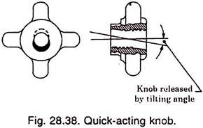
There are variations of the screw-type clamp. Numerous styles of commercial clamps have been developed to include advantages of the screw clamp and reduce its disadvantages. The efficiency of the screw clamp can be improved by using swing clamps, hook clamps and quick acting knobs. Swing clamps combine the screw clamp with a swinging arm which pivots on its mounting stud.
Quick acting knobs are made so that when pressure is released, they can be tilted and slid off a stud, (Refer Fig. 28.38). The knob is slid over the stud until it contacts the part. It is then tilted to engage the threads and turned until tight.
3. Cam-Action Clamps:
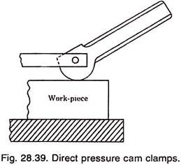
Cam-action clamps, when properly selected and used, provide a fast, efficient, and simple way to hold work, (Refer Fig. 28.39). Due to their construction and basic operating principles, the use of cam-action clamps is limited in some types of tools.
4. Hinged Clamps:
These utilise hinged lids for loading and unloading the components. Generally the clamp is made integral with the hinged lid. Fig. 28.40 shows an arrangement using combination of hinged clamp and hinged bolt.
This type of clamp is often required when it is necessary to move both the clamp and the bolt completely out of the way for the loading of component. The jig casing is designed such that the lugs are provided for locating the hinge pins. In order to save the operator’s time, a coil spring is used to hold the washer under the nut.
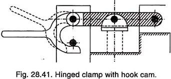
Fig. 28.41 shows an arrangement in which a hook cam is fitted which permits the job to be handled faster. It is only suitable for light clamping. The clamping lever is hinged on the clamping bar which, in its turn, is hinged on the fixture. Along the clamping bar is fitted a floating pad which holds the work and the clamping lever is then forced against a pin or other abutment fitted to the fixture.
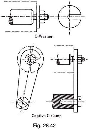
Fig. 28.42 shows commonly used type of clamping, particularly on drill jigs where drilling has to take place from a previously pored hole. The component is used over a locating pin and the clamping plate is swung into position under the nut.
The essential feature is that once the clamp has been removed, or swung away, the component can pass freely over the nut which means that the locking nut requires about one turn to release or lock the clamp and is, therefore, quick acting. In captive C-clamp, it remains fixed to the fixture and, therefore, can’t be lost whereas the C-washer can be secured to the fixture by means of a chain.
5. Two-Way Clamps:
Fig. 28.43 shows an example of rapid clamping in two directions from one screw. Clamping force is applied to the top and one side of the work piece. The clamp has a quick release action.
In this arrangement, the length of the levers should be approximately such that equal pressure is applied by each clamp at its clamping position. The top clamp is slotted at the end so that the whole of its clamping mechanism could be swung clear of the work.
Fig. 28.44 shows another method of clamping in two directions.
6. Wedge Operated Clamps:
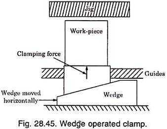
Fig. 28.45 shows the operation of wedge operated clamps in which the horizontal movement of the wedge causes upward vertical clamping force on the work piece. The wedge could be operated either manually by a screw or cam, or by pneumatic or hydraulic cylinder in which case automatic clamping of the work piece as part of a fully automatic machine cycle is possible.
Wedges having angle of 1 – 4° are self-holding type and normally hold the work without additional attachments. Large angel (self-releasing) wedges are used where large movement is required. In these wedge clamps, another holding device (came or screw) is required to hold and wedge the work piece in place.
7. Cam Operated Clamps:
These provide a fast, efficient, and simple way to hold work. If cam clamps apply pressure directly to work and work is subjected to vibration, then clamp may loosen and such clamp should not be used.
Direct pressure cam clamps must be positioned to resist the natural tendencies of the clamp to shift or move the work when the clamp is engaged. To prevent this movement, the clamp is always positioned such that work is pushed into the locators when pressure is applied.
The advantages of cam action can be obtained in indirect clamping method by using cam action rather than screw threads to bind strap clamps. (Refer Fig. 28.46). In this method, the possibility of loosening or shifting the work during clamping is decreased.
There are three basic types of cams used for clamping mechanisms: Flat eccentric, flat spiral, and cylindrical.
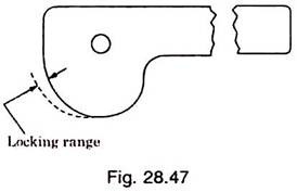
Flat eccentric cams are easiest to make and can operate in either direction from their centre position. The basic eccentric cam locks when the cam reaches its high centre position. This limits the full lock range to a rather small area. Movement beyond this high centre position automatically loosens the clamp. For this reason, eccentric cams and spiral type cams do not hold.
Flat spiral cams are the most common style of cam clamp used for jigs and fixtures. Commercial cam clamps use the spiral design rather than the eccentric because of its superior holding properties and wider locking range (Refer Fig. 28.47).
Cylindrical cams are also used in many jig and fixture applications. Cylindrical cams actuate the clamp by a lobe or through a groove cut into the surface of the cylinder.
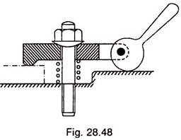
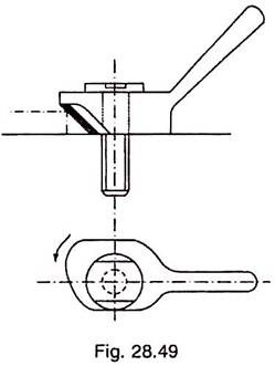
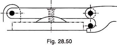
Generally an eccentric is used for clamping purpose, but where the locking range of the face is limited, there it may be dangerous and to avoid mishap in that case, as cam profile having an ample length of locking face and positive locking angle feature should be employed. Figs. 28.48, 28.49, 28.50, below show the various arrangements employing cam operated clamps.
Arrangement shown in Fig. 28.48 is utilised for holding components on which there is no great variation in position of the face to be clamped. The clamping is rapid and the tightening and releasing is done by a downward and upward movement of the clamping lever.
Cam contour may be either eccentric or spiral. It is found that eccentric cams get loosened by vibrations and do not lock properly; though these have the advantage of easy manufacturing.
The amount of eccentricity given should be such that cam rise is not too rapid and sufficient mechanical advantage should be obtained by gradual cam increment. For an eccentric cam to stay locked after clamping the work piece, the ratio of its diameter to eccentricity should be maintained between 14 to 16.
In the case of spiral cam, the normal reaction passes through the pivot point and thus provides certain locking action which is not possible with eccentric cam. In the design of spiral cam, two important things are the cam throw and rise.
Cam throw indicates the degrees by which the handle should be rotated to obtain the desired rise: the rise being the distance required for locking action. Usually 90° throw and 10° on either side as provision for inaccurate assembly is provided.
The rise should not be too rapid which otherwise would not make the locking convenient for the operator and the cam structure also becomes larger. Too small a rise is also not desirable which poses troubles when work piece varies in size.
In Fig. 28.49, the end face of the boss on the clamp is angled for the purpose of holding the work down, the cam and the face of the clamp pressing the work sideways against its location.
Fig. 28.50 shows hook cam type clamp recommended for light applications which maintain dimensional accuracy.
8. Toggle Action Clamps:
These are fast acting clamps. These have the natural ability to move completely free of the work, allowing for faster insertion/taking out of parts. The holding force to toggle clamps compared to the application force is very high. Fig. 28.51 shows the four basic clamping actions, viz. hold down, pull, squeeze, and straight line action.
Toggle clamps operate on a system of levers and three pivot points. When the clamp is locked, the pivots are nearly in line, the central pivot being slightly below the centre to insure positive lock. (Refer Fig. 28.52). When retracted, the pivots and levers are positioned as shown in Fig. (28.52) (b).
These toggle clamps can be used in a variety of ways with the special mounts, spindles, handles etc.
9. Power Clamping:
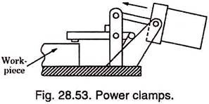
Power-activated clamps may operate under hydraulic power, pneumatic power, or with an air-to-hydraulic booster.
The power clamps have better control of clamping pressures. Wear on moving parts of the clamp is less, operating cycles become faster. Production speeds and efficiency are higher but initial cost is high. Fig. 28.53 shows a typical application of power clamp.
10. Chucks and Vises:
Commercially available chucks and vises with slight modifications of jaws to suit the job can be used for a variety of applications. Blank vise jaws and blank chuck jaws can be easily modified to suit practically every clamping need.
A great deal of time and money can be saved and the efficiency of the job increased by using standard chucks and vises for special tools.
11. Non-Mechanical Clamping:
Non-mechanical clamps like magnetic and vacuum chucks are used to hold parts which are difficult to be held by other devices because of their size, shape, or fragile nature. Magnetic chucks may either use permanent magnets or electro-magnets.
Magnetic chucks are obviously suitable for ferrous parts. For other materials, mechanical devices have to be used along-with magnetic chucks. Magnetic chucks and accessories are available in numerous styles and shapes.
For non-magnetic parts, vacuum chucks are suited. Vacuum chucks equalize the clamping pressure over the entire clamping surface. Vacuum chucks are suitable for almost every machining operation, particularly where uniform clamping is required. To clamp smaller parts, the exposed chuck ports can be covered with a mask, or closed by tightening the special part screws.


