In this article we will discuss about:- 1. Meaning of Jig Boring 2. Description of Jig Boring 3. Types 4. Machine.
Meaning of Jig Boring:
Jig borers are used for locating accurately and making the numerous holes necessary for jigs, fixtures, gauges and other precision parts. Although the single-point boring bar is the most important tool used in jig borers, yet drills, reamers and counter-borers are also used. The jig boring machine is developed from a locating machine and is relatively a new type of machine. This machine is rugged enough for heavy cuts and sensitive enough for light cuts.
Description of Jig Boring:
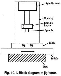
A jig borer has the essential elements of a vertical- spindle milling machine. For the sake of attaining high accuracy, it is generally built lower to the floor and is much more rigid and of accurate construction. On the base of it, a saddle is supported which moves in and out from the operator to the column.
ADVERTISEMENTS:
To supplement the saddle movement, a table is provided on it, which can move to right or left. It has a massive column which supports the spindle housing and is capable of moving up and down the column ways. Thus the third position adjustment is also achieved.
The spindle moves inside a quill and is supported by the housing or spindle head. In order to add to the rigidity of the machine tool, the quill is made capable of moving up and down inside the housing thus giving a telescopic mechanism.
In order to eliminate the lost motion for purpose of high accuracy and precision, the spindle, quill, and housing are manufactured under extremely careful and exacting conditions and to minimise the errors due to expansion, the housing is made of invar cast iron.
The spindle is hardened, ground, stabilised, and lapped, and pre-loaded ball bearings are used. The driving mechanism provided is capable of giving speeds ranging from about 30 to 1500 R.P.M. so that best cutting speed is available for each size of hole.
ADVERTISEMENTS:
For aligning the job and centering it, a dial indicator fitted on the spindle is used. Usually the operator locates the points etc., from either a finished edge or from a suitable hole while setting up for boring operation. The dial indicator is used to pick up the surface and then with reference to it, the spindle can be zeroed over the desired point.
Types of Jig Boring:
These can be classified according to the method of accurate location of hole.
Accordingly there are four systems of measurements:
(i) The precision lead-screw system.
ADVERTISEMENTS:
(ii) The end-measure system.
(iii) The scale and microscope system.
(iv) The electromagnetic system.
Each method has its own particular advantages and disadvantages and the selection depends upon the situation. The various factors to be considered for proper selection are price, delivery availability of spare parts, the size of the workpiece, preference for a particular type of measuring system desired for standardisation etc. However, much depends upon the operator’s ability and skill as far as accuracy is concerned.
ADVERTISEMENTS:
(i) The Precision Lead-Screw System:
In this machine, the feed and other motions are obtained due to rotation of lead screw just as in lathe. The system has the same disadvantages as in other cases, i.e. the accuracy of the lead screw is of the order of 0.005 mm and it varies from one place of lead-screw to another. The size (length) of the accurate lead-screw is limited (of the order of about 400 mm).
It has the advantage that the system is very fast and as it is enclosed in the body of the machine, it is not subjected to variations due to change in room temperature or operator handling.
(ii) The End-Measure System:
ADVERTISEMENTS:
The system used to locate the work accurately with end measures is the same as for other machines. The first step in it is to locate the workpiece from two finished edges 90° apart, one placed to the right of the table and the other placed to the front of the table.
With the help of a dial indicator in the spindle, the edges are made parallel to the table travel, and the workpiece is clamped securely without distorting it. A microscope is then mounted in the spindle and the table moved so that the cross-hairs are exactly centered over the intersection of the two finished edges or any other zero point.
Next the dimension at which hole is to be located is arranged by having suitable end measures for whole number and an inside micrometer for dimensional measurement and placing them together on the trough. The table is then moved till the built in dial indicator (acting like pressure gauge) resting against the end standard and inside micrometer reads zero. In the similar manner, the dimension in other plane is set.
It may be noted here that traversing screws for saddle and table have no connection with the measuring system, and backlash or wear in them has no effect on the accuracy of any setting.
The advantage of this is that it is very simple and easy to set up since the end measures are simple numbers. There is no particular limit to the size of machine. The disadvantage of the system is that the end measures rest in an open trough and are, therefore, subject to dirt and temperature variations due to surrounding temperature and handling them by operator.
(iii) The Scale and Microscope System:
The machine utilises a very accurate and precise scale fitted on the body of the machine and the microscope to take readings on the scale. The disadvantage is that it is very difficult to scribe a very fine line on the scale and the scale is subjected to surrounding temperature and also its temperature changes due to the body heat of the operator, due to which the scale precision is lost. The advantage of the system is that there is no wearing of parts. The readings are not affected by dirt.
(iv) The Electromagnetic System:
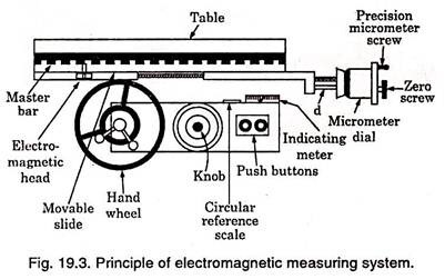
It consists of a solid master bar securely fastened beneath the worktable. The bar consists of a series of alternate notches about 125 mm wide and square projections 125 mm wide. The distance between the magnetic centres of adjacent projections or blocks is exactly 25 mm and the total accumulated error for the entire bar is not more than 0.5 µ m.
An electromagnetic head equipped with two balanced coils is fastened to a movable slide beneath the master bar and is capable of detecting the exact centre of each block (Refer Fig. 19.3). The head is further connected to an indicating meter and the movable slide is connected to a precision micrometer screw and dial.
To obtain basic 25 mm spacing, the table is moved until one of the blocks is exactly over the electromagnetic head and the indicating micrometer registers zero. Intermediate settings are obtained by the precision micrometer screw.
For doing any operation, the setting is done as follows: First the centre line of the machine is centered over either a machined edge or the centre line of the first hole by means of a dial indicator or some other satisfactory means. The micrometer is then set to zero position and locked. Then the zero-screw is turned until the indicating meter registers zero and it is then clamped.
This finishes ‘zeroing’ of the workpiece. Then for any setting, first the micrometer dial is moved by that amount to the right of the decimal point. After this the table is rapidly traversed the approximate distance of the remainder of the setting by using the circular scale and the handwheel is moved slowly until the meter reads zero.
Thus an advantage of this system is that the rapid movement from any even 25 mm to another even 25 mm can be taken quickly, making extreme care necessary only with the final setting. The disadvantage is that checking of accurate zeroing by electric meter is very difficult as compared to mechanical devices.
Jig Boring Machine:
Single Column Jig Boring Machine:
Vertical jig boring machines have robust bed and column castings. The cross slide moves on bed guideways (Y-axis) on linear bearings. The table moves on cross slide (X-axis) on linear bearings. Thus the machine is not only rigid but very smooth in operation, absolutely free from stick slip motion. The drive and guideway system offers low power consumption and precision positioning with ease.
Application Areas:
The machine is designed to bore precision holes with accurate centre distances. The centre distances are set in a cartesian co-ordinate system. Milling by end mills shank and milling cutters is possible.
The machine can be used for:
a. Threading,
b. Marking and
c. Inspection of linear dimensions.
By using the revolving tables one can work in polar co-ordinate system, as well as machine mutually perpendicular and inclined holes and planes.
Drive System:
Main spindle is driven by D.C. servo motor through a gear box to give stepless variation of spindle speeds from 10 to 2000 RPM. Table longitudinal and cross feeds (X, Y-axes) are powered by D.C. Servo motor, and vertical (Z axis) feed is available both for quill and headstock by a single motor. Thus all feeds are steplessly variable.
The plain rotary table is driven by D.C. motor. The universal rotary table (tilt able) is driven by A.C. motor for tilting. These tables are provided with micro ampere meters and induction pick-ups for precise positioning. Machine is equipped with ball screw drives for X and Y axes.
Measuring System:
The co-ordinate measuring system is by precision optical in X and Y axes. The resolution of the optical system is one micron. Digital Read Out system for X and Y axes is also possible. The resolution of the DRO system is 0.001 mm. In a full-fledged Numerically Controlled Jig Boring machine continuous path control and co-ordinate measuring in X, Y and Z axes is by optical grating scales displayed on the control system with 0.001 mm resolution.
Clamping:
Tool clamping is by means of compressed air operated automatically via push buttons. Axes clamping is also through pneumatics and automatic.
Standard Accessories:
i. Rotary indexing table with face plate
ii. Universal rotary table with face plate
iii. Centre locating microscope
iv. Centre locator with indicator
v. Fine feed tool holder
vi. Boring bars
vii. Collet holder with collets
viii. Spring locating punch
ix. Centre locating arbor
Specifications of Controller:
Features:
i. 3 Axis simultaneous linear interpolation
ii. 2 Axis circular interpolation (any two axes)
iii. Direct inch/Metric conversion
iv. Absolute/Incremental programming
v. Feed override 0—150%
vi. Full manual control with incremental job
vii. Full manual control with electronic hand wheel with a finest resolution 20 microns for one full rotation of the hand wheel
viii. Programme memory capacity 1000 blocks
ix. CRT display
Programmable Functions:
i. Nominal position values (absolute or incremental dimensions) entry in Cartesian co-ordinates or in polar co-ordinates
ii. Straight path 2½ D
iii. Circular arcs
iv. Rounding of corners derived from straights or arcs
v. Tangential approach, on a circular path, to a defined point on a contour
vi. 3 D-straight path, without tool radius compensation
vii. Tool numbers
viii. Tool length and radius
ix. Offset direction for tool radius compensation
x. Rapid traverse/feed rate (in mm/min. or 0.1 inch/ min)
xi. Auxiliary functions M 00 .. M 99
xii. Spindle speeds (2 decades BCD), programmed stop
xiii. Subprograms (8 x nesting)
xiv. Program part repeats
Fixed Machining (Canned) Cycles:
Pecking, Tapping, Slot milling, Pocket milling, Circular pocket, Mirror image, Datum shift, Dwell time.
Cnc Control Operation:
i. Manual operation-the control operates as a digital readout.
ii. Controlled operation with single block entry-each block is immediately positioned after key-in without entry into memory
iii. Program run/single block- block-by-block positioning with individual press START button.
iv. Automatic program run- after press of START button, complete run of program sequence until ‘program STOP’ or program end.
v. Programming- with linear or circular interpolation manually with stationary machine to program sheet or work piece drawing or externally via compatible data input/output {e.g. via Magnetic Tape Cassette Unit).
vi. With single axis positioning additionally by entering actual position data from position display (play back) during conventional manual machining.
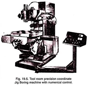
Tool Room Precision Co-ordinate Jig Boring Machines with Numerical Control (Refer Fig. 19.5):
Numerical Control Systems (Refer Fig. 19.6):
i. Keyboard programmable, central display screen showing all positions and active machine condition data as well as fault and error codes (in auto, manual and set up modes), data input in rectangular and polar co-ordinates.
ii. mm/inch calculator
iii. Programming format: %04, N04, G02, XL + 053, YL + 053, ZL + 053, CL + 053, ID053, JD053, KD053, F05, S04, T04, H04, R2, L5, M02
iv. Address code as per DIN 66025
v. Data input via punched tape, or keyboard.
vi. 64 blocks for length and radius.
vii. Standard graphic display.


