Various types of joints which are mostly used in pipes are as follows: 1. Spigot and Socket Joint 2. Expansion Joint 3. Flanged Joint 4. Mechanical Joints 5. Flexible Joint 6. Screwed Joint 7. Collar-Joint 8. Joint for A.C. Pipes.
Type # 1. Spigot and Socket Joint:
Sometimes this is called bell and spigot joint. This type of joint is mostly used for cast iron pipes. For the construction of this joint the spigot or normal end of one pipe is slipped in socket or bell end of the other pipe until contact is made at the base of the bell. After this yarn of hemp is wrapped around the spigot end of the pipe and is tightly filled in the joint by means of yarning iron up to 5 cm depth.
The hemp is tightly packed to maintain regular annular space and for preventing jointing material from falling inside the pipe. After packing of hemp a gasket or joint runner is clamped in place round the joint so that it fits tightly against the outer edge of the bell. Sometimes wet clay is used to make tight contact between the runner and the pipe so that hot lead may not run out of the joint space.
The molten lead is then poured into the V-shaped opening left in the top by the clamped joint runner. The space between the hemp yarn and the clamp runner is filled with molten lead. When the lead has hardened, the runner is removed. The lead which shrinks while cooling is again tightened by means of chalking tool and hammer.
The quantity of lead required per joint varies from 3.5 to 4 kg for 15 cm. dia pipe, to about 45-50 kg for 120 cm diameter pipe. This is somewhat slightly flexible joint; allow the pipes to be laid on flat curved without pipe specials. Now a days sometimes to reduce the cost of filling lead, certain patented compounds of sulphur and other materials are filled in the joints, but these materials do not provided flexibility equal to that of lead.
Type # 2. Expansion Joint:
This joint is used at such places where pipes expand or contract due to change in atmospheric temperature and thus checks the setting of thermal stresses in the pipes. The given Fig. 7.14 clearly illustrates expansion joint. In this joint the socket end is flanged with cast iron follower ring, which can freely side on the spigot end or plane end of other pipe an elastic rubber gasket is tightly pressed between the annular space of socket and spigot by means of bolts as shown in the figure.
In the beginning while fixing the follower ring some space is left between the socket base and the spigot end for the free movement of the pipes under variation of temperatures. In this way when the pipe expands the socket end moves forward and when pipes contract, it moves backward in the space provided for it. The elastic rubber gasket in every position keeps the joint water tight.
Type # 3. Flanged Joint:
This joint is mostly used for temporary pipe lines, because the pipe line can be dismantled and again assembled at other place. (see Figure 7.15)
The pipe in this case has flanges on its both ends, cast, welded or screwed with the pipe. The two ends of the pipes which are to be jointed together are brought in perfect level near one another and after placing one hard rubber washer between flanges are bolted.
ADVERTISEMENTS:
Placing of washer or gasket of rubber, canvas, copper or lead between the two ends of flanges is very necessary for securing a perfect watertight joint. This joint cannot be used at such places where it has to bear vibrations or deflection of pipes etc.
These joints are commonly used for jointing pumping stations, filter plants, hydraulic laboratories, boiler house etc. where it may be necessary to occasionally dismantle and reassemble the pipe lines. If the steel pipes are to be jointed by these joints, it is better to screw the separately cast flanges on the pipes and then they are jointed.
Type # 4. Mechanical Joints:
This type of joint is used for jointing cast iron, steel or wrought iron pipes, when both the ends of the pipes are plain or spigot.
There are two types of mechanical joints:
ADVERTISEMENTS:
(a) Dresser-Couplings:
It essentially consists of one middle ring, two follower rings and two rubber gaskets. The two follower rings are connected together by bolts, and when they are tightened, they press both the gaskets tightly below the ends of the middle ring. In this way the joint remains watertight. See Fig. 7.16.
These joints are very strong and rigid, and can withstand vibrations and shocks upto certain limit. These joints are most suitable for carrying water lines over bridges, where it has to bear vibrations.
ADVERTISEMENTS:
(b) Victaulic-Joint:
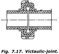
In this type of joint a gasket or leak proof ring is slipped over both the ends of the pipes as shown in the Fig. 7.17. This gasket is pressed from all sides on both the pipes by means of half iron couplings by bolts. The ends of pipes are kept sufficient apart to allow for free expansion, contraction and deflection. This joint can bear shocks, vibrations etc. and is used for cast-iron, steel or wrought iron pipe lines in exposed places.
Type # 5. Flexible Joint:
Sometimes this joint is also called Bell and socket or universal joint. This joint is used at such places where settlement is likely to occur after the laying of the pipes. This joint can also be used for laying pipes on curves, because at the joint the pipes can be laid at angle. This is a special type of joint.
The socket end is cast in a spherical shape as shown in Fig. 7.18. The spigot end is plain but has a bead at the end. For the assembling of this joint, the spigot end of one pipe is kept in the spherical end of the other pipe. After this retainer ring is slipped this is stretched over the bead. Then a rubber gasket is moved which touches the retainer high.
After it split cast iron gland ring is placed, the outer surface of which has the same shape as inner surface of socket end. Over this finally cast iron follower ring is moved and is fixed to the socket end by means of bolts as shown in the figure. From Fig. 7.18 it is very clear that if one pipe is given any deflection the ball shaped portion will move inside the socket, and the joint will remain waterproof in all the positions.
Type # 6. Screwed Joint:
This joint is mostly used for connecting small diameter cast iron, wrought iron and galvanized pipes. The ends of the pipes have threads on outside, While socket or coupling has threads on the inner side. The same socket is screwed on both the ends of the pipes to join them. For making water tight joint zinc paint or hemp yarn should be placed in the threads of the pipe, before screwing socket over it.
Type # 7. Collar-Joint:
This type of joint is mostly used for joining big diameter concrete and asbestos cement pipes. The ends of the two pipes are brought in one level before each other. Then rubber gasket between steel rings or jute- rope soaked in cement is kept in the grove and the collar is placed at the joint so that it should have the same lap on both the pipes. Now 1: 1 cement mortar is filled in the space between the pipes and the collar as shown in Fig. 7.20.
Type # 8. Joint for A.C. Pipes:
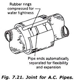
For joining small diameter A.C. pipes, the two ends of pipes are butted against each other, then two rubber rings will be slipped over the pipes and the coupling will be pushed over the rubber rings as shown in Fig. 7.21. The rubber rings make the joint water-proof.


